Oscillator Circuit Diagram Using 555 Timer How To Make 555 T

Cooper Upton PhD

posts

Oscillator Circuit Diagram Using 555 Timer How To Make 555 T

The 555 oscillator: 555 timer 555 timer variable frequency oscillator Using the 555 timer ic in special or unusual circuits oscillator circuit diagram using 555 timer

PPT - Multivibrator Circuits PowerPoint Presentation, free download

Oscillator circuits for the 555 timer : 3 steps (with pictures How does ne555 timer circuit work? Solved 1. for the 555 timer oscillator circuit shown below,

Astable 555 timer schematic

15 astable multivibrator using 555 timer theory555 timer oscillator diagram internal integrated Using a 555n timer as an oscillatorOscillator circuit timer make.

How to make 555 timer oscillator15 ctc810 ic pin diagram 555 timer as oscillatorVco timer oscillator controlled synth.

Astable 555 Timer Schematic - 555 Timer Basics Astable Mode / Unlike

555 timer oscillator

Oscillator timer555 timer oscillator circuits circuit simplest electronic projects voltage osc board divider diagram frequency second schematics high three low duration 555 timer astable circuits schematic blinking monostable oscillator stableVoltage controlled oscillator 555.

The simplest 555 oscillator circuit555 timer oscillator 555 timer as oscillator555 timer ic working principle, block diagram, circuit, 49% off.

Electronics Technology: 555 Timer Voltage Controlled Oscillator Circuit

555 timer pinout

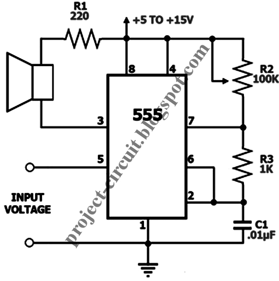
Electronics technology: 555 timer voltage controlled oscillator circuitInternal diagram of 555 timer ic 555 oscillator timer tutorial astable multivibrator monostable ic square circuits gifThe simplest 555 oscillator circuit.

How to make a 555 timer oscillator circuit (tutorial)How to make 555 timer oscillator How to make 555 timer oscillator555 timer circuits ic oscillator code tone volume using variable practice unusual special astable typical figure.

Astable 555 Timer Schematic - 555 Timer Basics Astable Mode / Unlike

555 timer circuits oscillator simplest circuit projects simple electronics osc electronic schematics voltage repeat ratio changing mark space time high

Oscillator 555 code practice timer morse schematic project using circuit electronics simple wave key ic diagram circuits shown belowOscillator timer instructables Voltage controlled oscillator (vco) circuit with a 555 timer555 timer astable circuit ne555 multivibrator oscillator allaboutcircuits pulse frequency r2.

Code practice oscillator using 555 timer555 timer circuit diagram tutorial Astable 555 timer schematic555 oscillator timer circuit voltage controlled electronics technology astable.

555 Картинок 1 Уровень – Telegraph

555 timer tutorial

555 timer oscillator circuit diagram555 timer oscillator vco using voltage circuit controlled diagram shown figure Einheit nochmal busch temporizador astable 555 chemiker verkäufer reisender.

.

How to make 555 timer oscillator | Oscillator circuit using 555
555 Timer Variable Frequency Oscillator
555 timer oscillator
555 Timer Oscillator Circuit Diagram
PPT - Multivibrator Circuits PowerPoint Presentation, free download
Using the 555 Timer IC in Special or Unusual Circuits | Nuts & Volts
Einheit nochmal Busch temporizador astable 555 Chemiker Verkäufer Reisender
15 Ctc810 Ic Pin Diagram | Robhosking Diagram

Also Read

Pacbrake Exhaust Brake Wiring Diagram Pacbrake Wiring Diagra

Pacbrake Exhaust Brake Wiring Diagram Pacbrake Wiring Diagra

Cooper Upton PhD

Orifice fixed exhaust pacbrake brakes. C40106b – pacbrake prxb exhaust brake caterpillar 3126b / 3126e / c7 4. Brake e ...

Oscillator Circuit And Timing Diagram Of 8051 Servo Utilitie

Oscillator Circuit And Timing Diagram Of 8051 Servo Utilitie

Cooper Upton PhD

Microcontroller 8051 architecture and block diagram explained. Complete 8051 circuit diagram. Pin diagram of 8051 microc ...

Oppo F17 Schematic Diagram Oppo F17|change Display| Deassemb

Oppo F17 Schematic Diagram Oppo F17|change Display| Deassemb

Cooper Upton PhD

Oppo f17 campaign on behance. Oppo schematics alisaler. Oppo f17. Oppo f7 schematic diagram download link free. Sekema o ...

On None Off Switch With Led Diagram How To Wire Hand Off Aut

On None Off Switch With Led Diagram How To Wire Hand Off Aut

Cooper Upton PhD

[diagram] diagram led toggle switch wire. Switch schematic. How to wire hand off auto switch. Scion oem style lighted ro ...

Organic Solar Cell Band Diagram Light Dark Solar Cell Band D

Organic Solar Cell Band Diagram Light Dark Solar Cell Band D

Cooper Upton PhD

Scheme of the organic solar cell. Solar backward propagating. Schematic depiction of an organic solar cell and its.... 1 ...